4/Flux Resource Model
The Flux Resource Model describes the conceptual model used for resources within the Flux framework.
Name |
github.com/flux-framework/rfc/spec_4.rst |
Editor |
Mark Grondona <mgrondona@llnl.gov> |
State |
draft |
Language
The key words “MUST”, “MUST NOT”, “REQUIRED”, “SHALL”, “SHALL NOT”, “SHOULD”, “SHOULD NOT”, “RECOMMENDED”, “MAY”, and “OPTIONAL” in this document are to be interpreted as described in RFC 2119.
Goals
The Flux Resource Model provides a common conceptual model for resources described and managed by the Flux framework and its components. The goals of this model are to:
Develop a generalized, extensible model for resources within the framework such that all present and future resource types fit the model
Provide a common configuration scheme for these resources
Provide a common storage, access, modification and discovery APIs for managing resource information
Background
As in traditional resource management software, the Flux framework requires a method for the description, configuration, tracking, and assignment of consumable and other resources in the system being managed. The Flux Framework, however, requires a more generalized and flexible definition of resources and overall approach. This document describes the basic concepts used to describe each individual resource and its relationship with other resources. Further, it illustrates how Flux uses these concepts to model some of the common high performance computing (HPC) resources in relation to other resource management components. We term the model for describing resources in Flux The Flux Resource Model.
The Flux Resource Model
The Flux Resource Model combines two basic concepts to describe individual resources and various relationships among them.
The concept to describe each identifiable resource is called resource pool. A resource pool is a group of one or more indistinguishable resources of a same kind. Each resource in a pool cannot be individually identified, and therefore, the resources in the pool are collectively represented as a quantity. 32GB memory on a compute node, for instance, MAY be described as a memory-resource pool with its pool size being 32 (i.e., 32 equal chunks of 1 GB memory).
One of the benefits of introducing the pool concept is flexibility in describing a resource with different levels of detail. When a resource needs to described at coarse granularity, it can be pooled together with other resources of the same type. Conversely, when finer granularity is required, it can be promoted to its own individual pool. If the compute node consists of 2 sockets and non-uniform memory access performance between them is an important consideration, 32GB memory can be modeled as 2 distinct memory-resource pools instead, each on a socket with its pool size being 16 (i.e., 16 equal chunks of 1 GB memory).
A resource pool with size 1 SHALL be the finest granularity at which a resource can be described. Although this is identical to describing the resource as a scalar, we SHALL still call it a resource pool to avoid introducing a new concept. When a distinction is needed, a pool with size 1 SHALL be called a “degenerate resource pool”.
The second concept borrows from graph theory to describe relationships among such individual resource pools. A graph consists of a set of vertices and edges, where each vertex represents an individual resource pool and an edge a certain relationship between them.
Each edge SHALL be either directional or bidirectional and have a type as well as a subsystem name such that the union of the set of all edges with a same name and the set of all vertices connected by these edges SHALL represent a unique subsystem of resources (e.g., a compute subsystem, a parallel I/O subsystem, a power subsystem, etc).
Resource Pool Data Model
This section describes the resource pool data required to be stored, tracked, and queried. Resource pool data SHALL be composed of base data and OPTIONAL extended data. The base data captures the static properties of the resource pool instance being modeled so that it SHALL include, but be not limited to:
Type
UUID (Unique ID for this resource)
Basename
Name
ID (OPTIONAL numeric ID to be appended to basename to get name)
Properties (static properties associated with this instance)
Size (Total number of resources in this pool)
Units (OPTIONAL units associated with the
sizevalue)
The default value for basename SHALL be the type. The default value for
name SHALL be a concatenation of basename and ID, or just basename
when the ID value is not assigned.
The value for name SHALL support arbitrary resource attributes and
properties (e.g. a system might have node names formatted like
“node-${frameid}-${rack}”).
The value for properties SHALL support multiple identifying
properties which could be used to uniquely characterize the resource.
On the other hand, the OPTIONAL extended data SHALL enable a user, typically a management service such as a scheduler, to extend, store and update its own data along with the base data of the target resource pool instance.
It MAY include, but be not limited to:
Tags (dynamic list of tags)
State (e.g., up, down, degraded, failing, unknown, null)
Scheduling state data such as job allocations and reservations
Graph Data Model
A graph consists of a set of vertices and edges. The Flux Resource Model uses a vertex to represent a resource pool. However, it is RECOMMENDED to avoid embedding all of the resource pool data (i.e., base and extended data) directly into the vertex itself. Instead, only a minimal set of metadata on the resource pool is RECOMMENDED to be embedded directly within to the vertex while keeping a reference to the pool data itself. The metadata MAY pertain to traversal and search optimization: e.g., optimizing the retrieval of vertices of certain types of resources, speeding up graph traversal by eliminating unnecessary descents of a tree graph, etc.
An edge SHALL have data indicating its direction(s), type and belonging subsystem name. The direction and type of an edge SHALL provide a semantic meaning to the relationship between its connecting vertices, and the name SHALL identify a subsystem this edge belongs to.
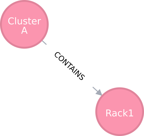
An edge capturing a “has-a” relationship
As shown in Figure 1, for example, the edge of the “CONTAINS” type represents the “has-a” relationship: i.e., Cluster A has a rack called Rack1.
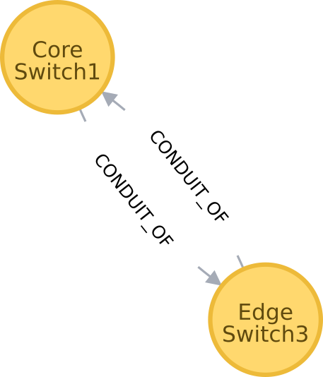
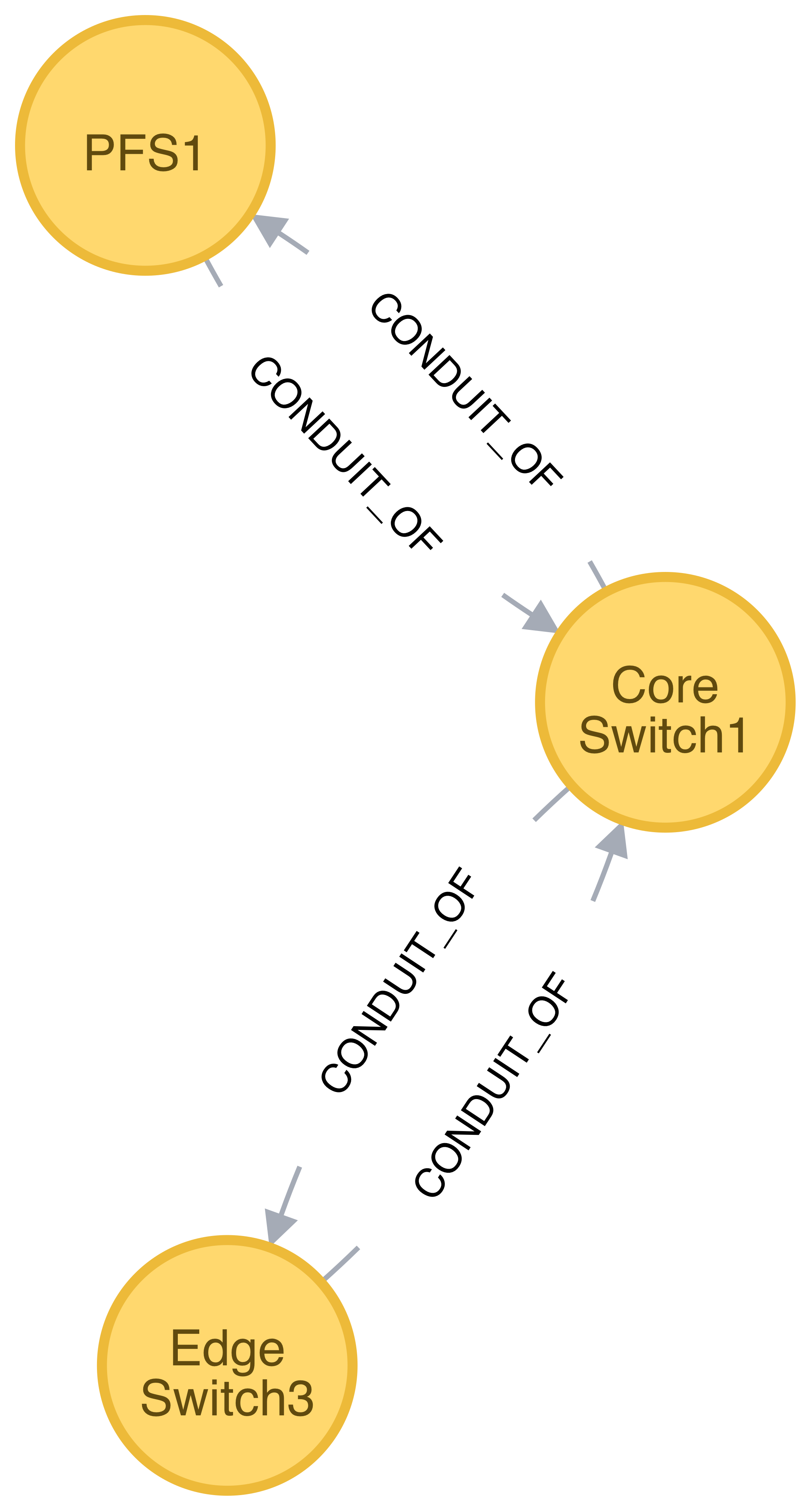
Edges representing “conduit-of” relationships
Similarly, as shown in Figure 2, each edge of “CONDUIT_OF” type represents a directional flow relationship: i.e., EdgeSwitch3 is a conduit of CoreSwitch1 through which data flows. A bidirectional relationship MAY be represented either as a single edge with arrows in the both ends or two opposite directional edges.
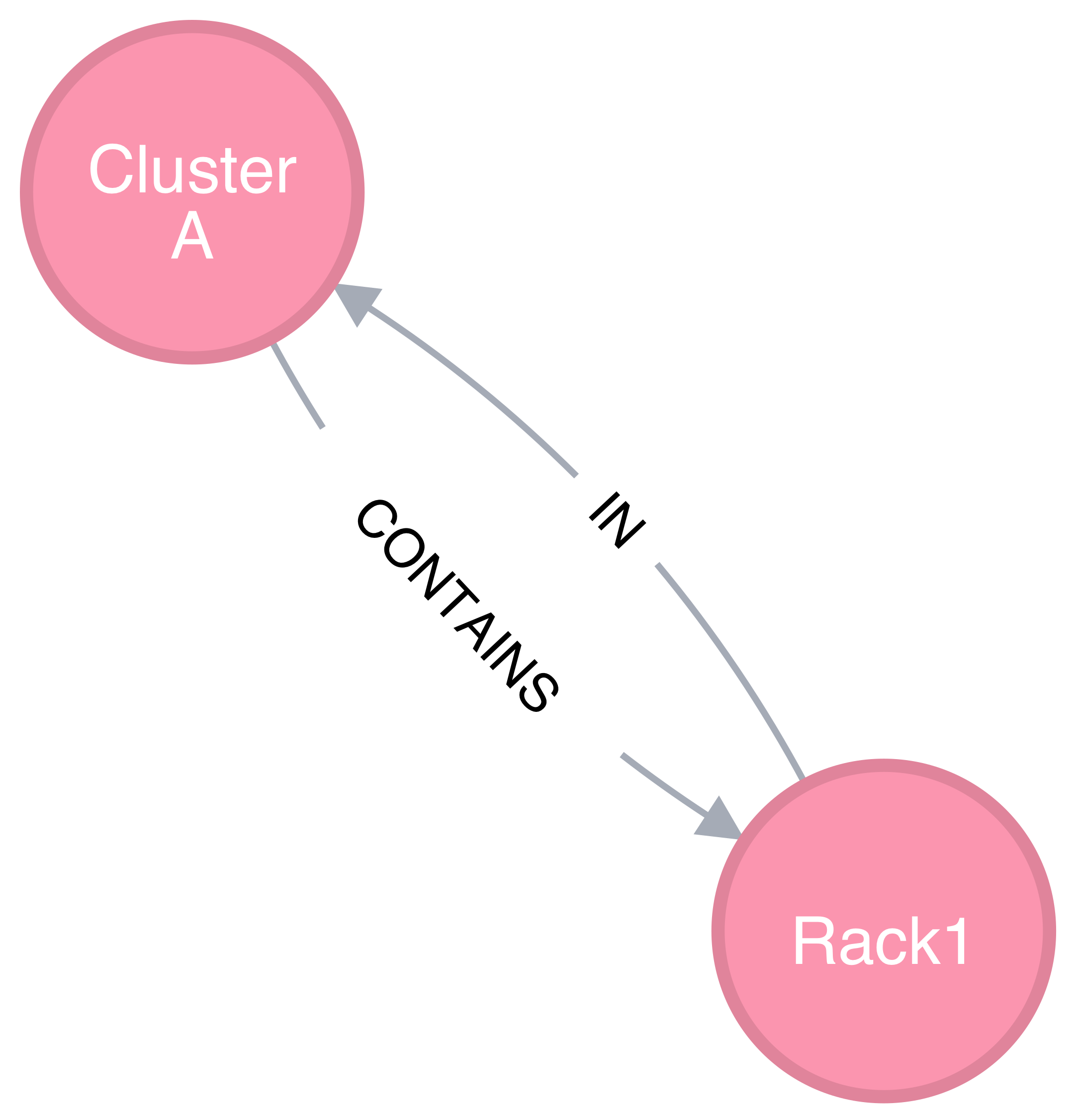
Opposite relationship
A directional relationship MAY be accompanied not only by the same type but also by the opposite type in the opposite direction. For example, a directional “CONTAINS” edge MAY be accompanied by an “IN” edge in the other direction, as shown in Figure 3.
Finally, the subsystem name of an edge SHALL be given such that the union of the set of all edges annotated with a same name and the set of all vertices connected by these edges represent a subsystem of resources. Both edges in Figure 3 MAY be named “physical hierarchy” if this graph belongs to that named hierarchy. Similarly, if the graph shown in Figure 2 is a part of the I/O data path of a parallel file system, PFS1, its name MAY be “PFS1 I/O bandwidth hierarchy.”
Common Patterns
The Flux Resource Model SHALL support a range of resource sets, from all of the resources in the center to a small subset allocated to one Flux instance. In addition, the Flux Resource Model SHALL support management operations at multiple granularity. In such a scheme, the higher the Flux instance is in the Flux instance hierarchy, the coarser resource granularity it MAY be configured to operate at. For example, a higher-order Flux instance MAY be configured to operate at the racks and aggregates on their containing nodes while a lower-level instance MAY actually operate at the nodes and cores as the finest resource granularity.
The following provides common examples to illustrate how Flux composes two basic concepts to model some of the common HPC resources.
The Composite Resource Pool
The dominant form of the Flux Resource Model is called composite resource pool, the combination of a composite type (i.e., resources with 0 or more children and at most one parent, arranged in a hierarchical “has-a” graph relationship), and a resource pool.
Borrowing from an object-oriented design pattern, the composite resource pool leads to the natural representation of resources as a hierarchy of individual or pooled resources bound to a root which will typically be a “cluster” or “center” resource.
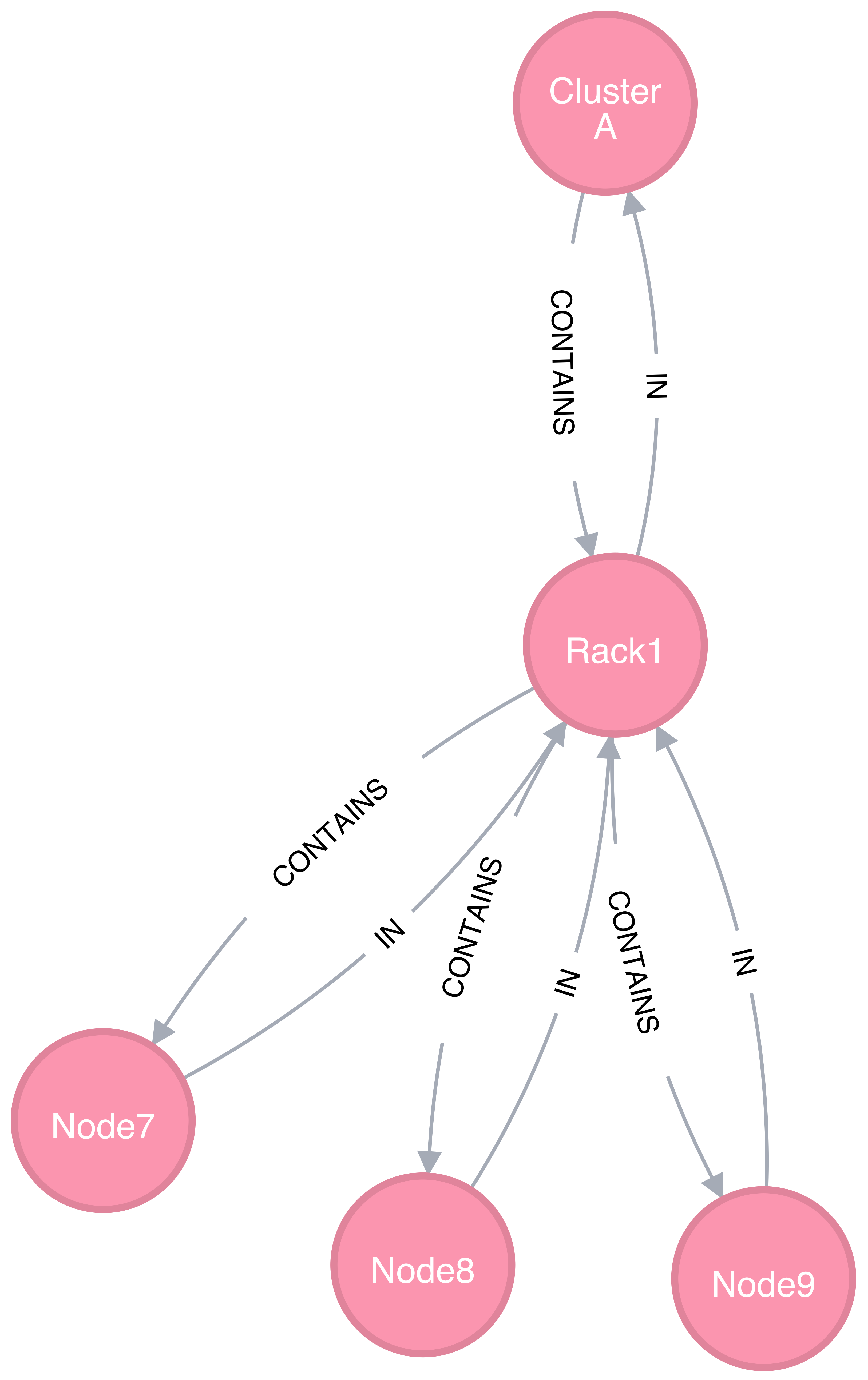
Modeling a containment hierarchy using the composite resource pool
Figure 4 shows a simple example of a composite resource pool representing a compute-hardware containment hierarchy.
Use of the composite resource pool in Flux has the following properties:
Groups of related resources are treated the same as a single instance
A subset of a composite resource pool is a valid composite resource pool
Composite resource naturally describes resources in a “has-a” relationship
High level resources can be created piece-wise from base resource types.
The Channeled Resource Pool
As HPC centers are becoming increasingly data- and power-constrained, the Flux Resource Model MUST be flexible to be able to model how data and/or power flow through its distribution units (e.g., a high performance switch for data and a power distribution unit for power). One specific form of the Flux Resource Model to represent the notion of a flow is called channeled resource pool. Here, two resource pool instances, each representing a distribution capacity of a flow, are related under a channel-of or conduit-of relationship.
Modeling a file I/O bandwidth hierarchy using the channeled resource pool
Figure 5 shows how the I/O bandwidth subsystem of a parallel file system, PFS1, can be modeled using this form. The resource pool in each vertex describes its distribution capacity and each edge represents which direction data is distributed to.
Using this representation, an I/O bandwidth-aware scheduler MAY allocate the bandwidth capacity required by a job on all of the distribution units that lie along the data path up to PFS1 when the platform is I/O bandwidth-constrained.
Unifying Different Patterns under the Same Model
Because any specialized form of a resource subsystem SHALL be itself built out of the same basic concepts, the Flux Resource Model SHALL be capable of easily combining different patterns into a unified form.
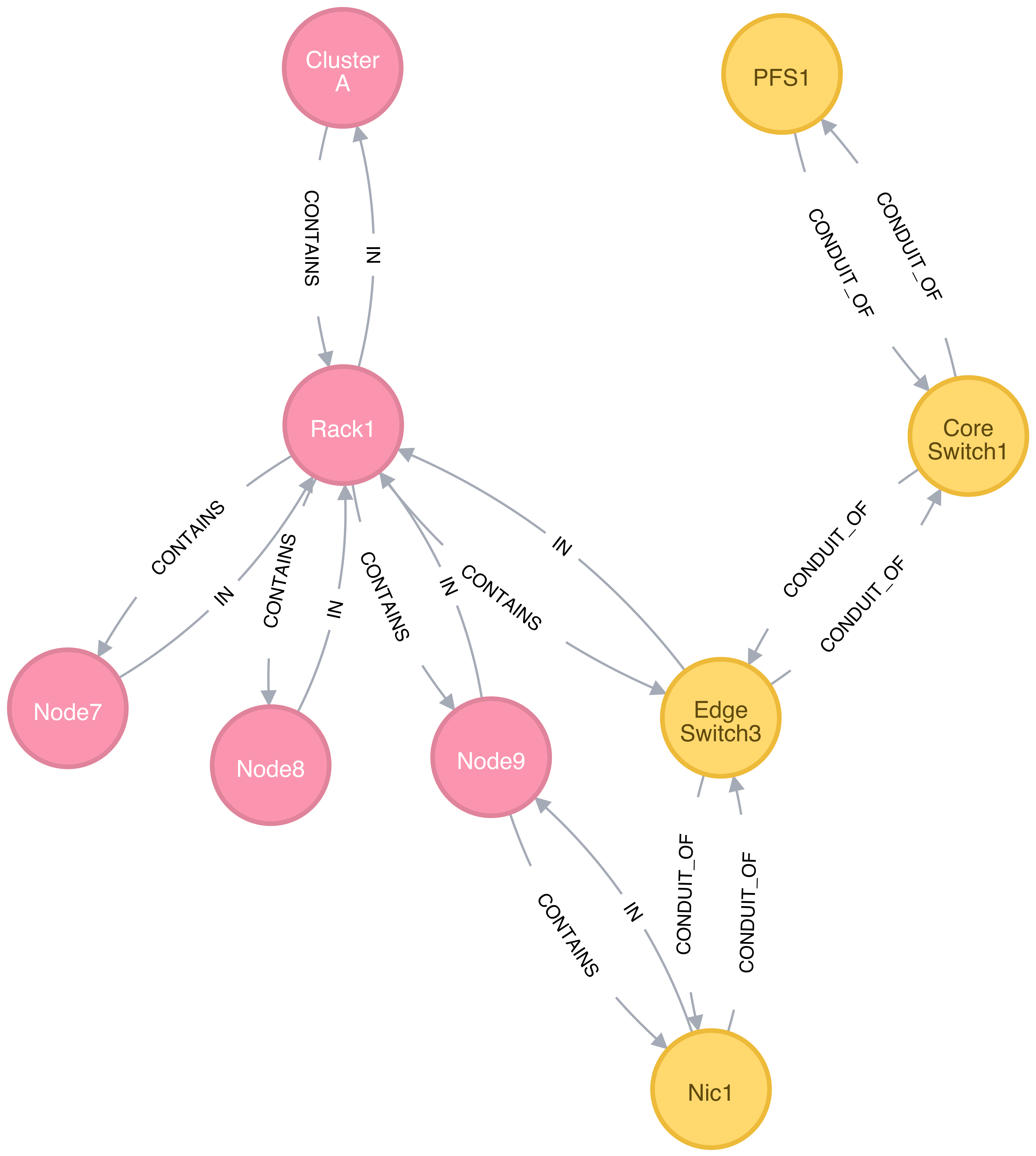
Unified graph
Figure 6 shows how the above two different forms of the Flux Resource Model can be seamlessly represented under the same paradigm. While simple, this example shows how the Flux Resource Model generalizes ways to model any resources, their individual relationships, and perhaps more importantly subsystems of these resources.
Abstract Interfaces
The abstract interfaces of the Flux Resource Model SHALL include, but not be limited to the following. These interfaces are again broken down by two fundamental concepts of the Flux Resource Model: resource pool and graph. The implementors of the Flux Resource Model MAY use this as a guide to determine the proper abstraction level exposed by the implementations.
Resource Pool
When operating on a resource pool as an object, the following methods SHALL be supported. The majority of methods are accessors.
- Getters
Query both the base and extended data of the resource pool, including its size.
- Setters
Update certain base and extended data, which includes “Tag (K, [V])”, a method for tagging a resource pool object with arbitrary key (K) and OPTIONAL value (V) pairs, if the extended data includes Tags, and “State”, a method for setting the state of the resource, if state is included in the extended data.
- Matching support
Support various comparison operations from the filters that are being invoked by a walker (See the Graph subsection). Getters SHALL expose sufficiently detailed information so the evaluating filter can match on both base and extended data (e.g., tags, properties, size, type, name, basename, ids, etc).
Graph
The following are the primary abstract types and their roles as relevant to the graph.
- Walker
Provide generic ways to traverse the graph, visiting a subset of its vertices with a specific traversal pattern. It is passed in the starting vertex and the name of a subsystem (e.g., the root vertex of a compute-hardware containment hierarchy or an I/O bandwidth hierarchy) from which to walk. In particular, on a tree hierarchy, preorder and postorder visiting patterns SHALL be supported, and a user MAY be able to register with it pre- and/or post-order callbacks, or “filters”, which are invoked by the walker on each visit event. The filters MAY be passed in either from within the same service space or from a remote service space. The implementation that supports the remote filter passing facilitates providing the the Flux Resource Model as a standalone “Resource” service.
- Pruning Filter
Allow a user of the walker to continue or stop further traversal from the visiting vertex. On a tree hierarchy, this filter is called back by the walker on each preorder visit event, and its return code influences the walker’s next traversal action.
- Evaluating Filter
Allow a user to evaluate the resource pool data of the visiting vertex. In particular, on a tree hierarchy, it is invoked by the walker on each postorder visit event. This filter will typically calculate the matching score of the visiting vertex, and if the score satisfies the criteria, it pushes the vertex into an accumulator that is capable of tracking the selected vertices in descending score order. In addition, an evaluating filter can initiate a new sub-walk into connecting vertices that belong to a subsystem different from the currently walking subsystem. In this case, a different walker and filters MAY be used.
- Accumulator
Allow an evaluating filter to store and keep the matching vertices in their sorted score order.
- Serializer
Allow for serializing/deserializing a subset of vertices along with their resource pool data. Allow for transmission of this data over the wire, saving state to a file, etc.